That should be "sticky-d some were where it can easily be referenced back too
Floating Depression?
-
Flash
- Posts: 778
- Joined: Thu Feb 25, 2010 3:39 pm
Re: Floating Depression?
Grate post Rick!
That should be "sticky-d some were where it can easily be referenced back too
That should be "sticky-d some were where it can easily be referenced back too
Gordon
-
BigBro74
- Posts: 41
- Joined: Sun May 29, 2011 7:52 pm
- Location: central Illinois
Re: Floating Depression?
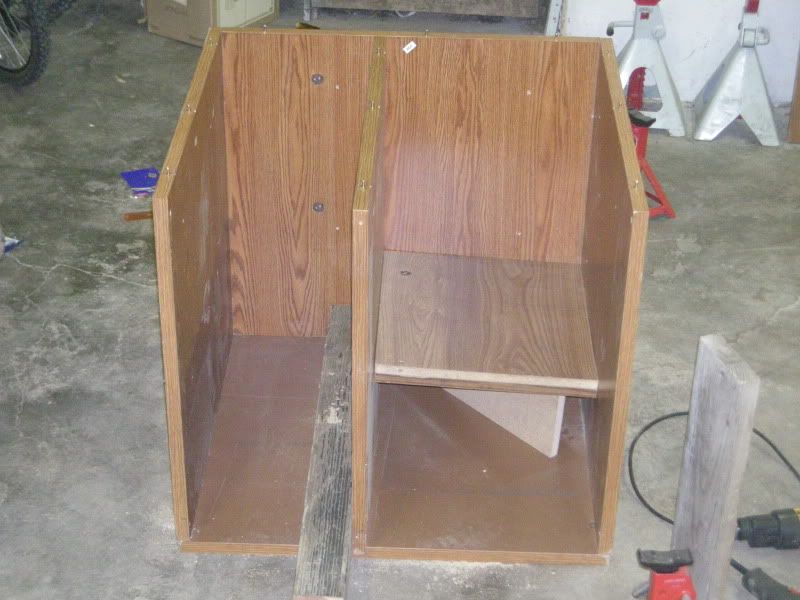
got a couple to go in. The sizing is somthing new for me!
the last shows the orifice plate, i couldn't make one of the plate by itself go.
might have to try sometime on lower res or farther away
Jason
the last shows the orifice plate, i couldn't make one of the plate by itself go.
might have to try sometime on lower res or farther away
Jason
You do not have the required permissions to view the files attached to this post.
Jason
-
Flash
- Posts: 778
- Joined: Thu Feb 25, 2010 3:39 pm
Re: Floating Depression?
Yeah or you can up load then to photobucket(you can get an account for Free) and then just link then here like this.
Gordon
-
blaktopr
- Posts: 622
- Joined: Sat Feb 20, 2010 9:27 pm
- Location: Central NJ
- Contact:
Re: Floating Depression?
Flash, I now know where my 80's Soundesign stereo cabinet went 

Chris Sikorski
Chris@wetflowtech.com
Totallywirednow.com
Chris@wetflowtech.com
Totallywirednow.com
-
BigBro74
- Posts: 41
- Joined: Sun May 29, 2011 7:52 pm
- Location: central Illinois
Re: Floating Depression?
I Sent off for that book by Dalton too, should be good info. Maybe more floating depression ideas?
Anyone any idea about those headflow #'s?
Anyone any idea about those headflow #'s?
Jason
-
coulterracn
- Posts: 450
- Joined: Wed Feb 24, 2010 5:44 am
- Location: Mississippi Gulf Coast
- Contact:
Re: Floating Depression?
Stan Weiss has some flow numbers from different head porters posted on his websiteBigBro74 wrote:Anyone any idea about those headflow #'s?
http://users.erols.com/srweiss/tablehdc.htm#Chevy
Go to the Chevy section and look for the casting number you're testing for comparison
Ray
My Flowbench is better than their's
-
Flash
- Posts: 778
- Joined: Thu Feb 25, 2010 3:39 pm
Re: Floating Depression?
AND IT STILL WORKS!blaktopr wrote:Flash, I now know where my 80's Soundesign stereo cabinet went
But most of the time, it has this bad air rushing sound, and i thing it has a bad speaker. It screeches some times.
Gordon
-
BigBro74
- Posts: 41
- Joined: Sun May 29, 2011 7:52 pm
- Location: central Illinois
Re: Floating Depression?
I look on stans site A LOT! It is a good site!
was more looking for some insight as to whether they numbers look terribly optimistic from a person who had done a few like it. Ray, maybe you know about how castings like that typically flow and at what ranges it might be different from what you typiaclly see. On stans site there are only a couple 461 castings and ,if memory serves not exact casting/valve. The port job I know only is only as good as the schmuck with the grinder (me).The 461 heads are now on a 2bbl 355 stockcar. The driver says good things.
was more looking for some insight as to whether they numbers look terribly optimistic from a person who had done a few like it. Ray, maybe you know about how castings like that typically flow and at what ranges it might be different from what you typiaclly see. On stans site there are only a couple 461 castings and ,if memory serves not exact casting/valve. The port job I know only is only as good as the schmuck with the grinder
Jason
-
jfholm
- Posts: 1628
- Joined: Fri Feb 19, 2010 7:36 pm
- Location: Grantsville, Utah 45 min west of Salt Lake City
Re: Floating Depression?
Your flow numbers for the 461 heads seem to be right in the ball park. That seems to be around the numbers we used to get. I like your .300 lift numbers. I always want strong mid lift numbers. I always check for average flow for the head also. I total the flow from every test lift setting and then divide it by the number of lift increments. That way I get a better comparison from head to head on which is really better. You may have one that has great high lift numbers but is a turd at lower lifts. Those heads do not always perform well. I like heads with strong mid range flows and your .300 lift at 195 cfm is pretty darn good.
John
John
-
1960FL
- Posts: 1340
- Joined: Fri Jan 08, 2010 10:36 pm
- Location: Maryland
Re: Floating Depression?
Jason;
Right now with your setup I would not really look at the numbers for comparison to a know orifice or Pito bench as there are just too many variable and no one standard.
In normal testing we use the Depression as one standard say 10” or 28” and a know flow orifice or standard tube diameter (Pito). With these we do not have to take into consideration what the motor is doing or what the line voltage is as we are moving the air through a known restriction. In your case the test object is the only restriction and you are comparing that to a supposed orifice and trying to correlate to CFM, but we still have the motor and line voltage issue we cannot account for.
So to help improve the accuracy of your test apparatus I would start by obtaining a sharp edge orifice from Bruce of known flow say 100 cfm at 28” .62CD, then obtain a variac if you can a HF motor speed controller wont work as it is not outputting the same AC voltage as line voltage and will throw your numbers off. A variac will actually vary the AC line voltage without modifying the AC wave form just attenuating the peak voltage. A variac will normally allow you to step the peak voltage up to say 140AC also. I would then test the orifice plate at 1 volt increments from say 125VAC down to 100 VAC all the time flowing the fixed orifice. Build a table of line voltage, motor voltage, depression measured. With this and some simple algebra you will be able to create a voltage Flow correction Factor. The reason I am saying this is I do not believe that you can just use a standard ratio of say 114/120 as these vacuum motors are not linear, and since line voltage comes into play in your math you will need a validated correction factor.
Just something to think about
Rick