Page 20 of 34
Re: SF Sizes
Posted: Fri Nov 25, 2011 7:10 pm
by 65mustang393
Chad Speier wrote:Yep and some believe (SF for example) that the cd stays constant at .60...
2.044" dia = 0.022787 sq feet = "A"
C= Cd = .62
K= 4005
P= 28" water pressure
"V" = .60 x 4005 x 5.2915 = 12715.474 feet/min
Q=AV
Q=0.022787 sq feet x 12715.474 feet/min = 289.75 cu feet/min
What did it flow??????????????????????????????????????????????????????????????????
Now do you want to know why the bench flows less than it should?
It flowed 289.6 on the intake and I think you just answered your own question with the 0.6 Cd.
Here's how I see it... whether or not PTS benches cal down or SF benches cal up the end result is the gap between numbers shrinks (on the same head) and the results from the benches can be more realistically compared to each other (within reason). The example where the PTS is 21 cfm higher than the SF at 0.4" was an eye opener. It was almost 8%. DM's SF bench read the same as the PTS, but didn't you post earlier that he sharpy'd his cal numbers to match the PTS?
I'm asking earnest questions, so don't bash me... and don't call me stupid or question my integrity or anything like that and I'll gladly return your kindness.
Re: SF Sizes
Posted: Fri Nov 25, 2011 7:36 pm
by Brucepts
65mustang393 wrote:I'm asking earnest questions, so don't bash me... and don't call me stupid or question my integrity or anything like that and I'll gladly return your kindness.
I think you all are doing quite well

I understand the emotions on both sides . . . this has been an enlightening thread
Re: SF Sizes
Posted: Fri Nov 25, 2011 8:15 pm
by Chad Speier
Darin doesn't own a PTS anything, except some plates I gave him. He has a 30 year old SF600 and a Audie. He uses the formula I posted and sets the bench at that.
Here is the problem as I see it and I just proved it to myself. Bruce is 100% correct in using .620 for a SHARP EDGE orifice. The reason the gap is there is because we are using a SHARP EDGE plate on a bench that is designed with a square edge orifice plate that was calibrated with a .60 square edge plate at 10"!!! THAT is the problem. We are trying to calibrate something that wasn't properly done from the word go! Maybe why the 18 plate kit????
I took a 1.875 square edge today and guess what. 13" across the plate! Manometers showed what they should. Got to 28" and it went 6 low.
The manometer will never match the electronics. Why do you think I use the formula I do? Where do you think it came from? My bench could read even higher but I choose the SF way of calibrating.
I stand by my comments.
From HB2
According to the instruction manual, the factors for intake and exhaust flow should be applied when testing at any test pressure other than 25”H2O where the factors are listed as 1.000. Unfortunately, most operators do not use the simple arithmetic. So for years operators have simply used the indicated flow numbers the benches provided without applying any correction. This doesn’t cause too much of a problem until it is time to check the calibration with any number of methods that are available in the marketplace.
Re: SF Sizes
Posted: Fri Nov 25, 2011 10:49 pm
by blaktopr
Mustang, how is your velocity probe reading. Based at your current setup. Can you probe an easy area like the pinch trying to keep at a steady depression. Does the measured and probed areas match when using the calculated measurement based on your current CFM numbers.
EX. If I probe an area and get 302 FPS based on my bench cfm, I am at 2.700 sq in.
If I were to use CFM from your bench of my port and apply the cfm # to the CSA calc, I may get around say 2.62. When I measure my port without radius removed I get 2.8. Corner radius about .250 is minus .054. Plus I have a little extra radius on the top and bottom. For sake of argument, lets call it minus .075. So 2.8-.075 is 2.725. So then if that the case, I would question the CFM the bench was showing.
Re: SF Sizes
Posted: Sat Nov 26, 2011 1:25 am
by 65mustang393
I'll post some pitot airspeed vs CSA examples tomorrow.
If memory serves me right, the airspeed was a little high on the SF300 vs the expected speed for CSA. The SF600FC is probably more of the same.
Re: SF Sizes
Posted: Sat Nov 26, 2011 1:38 am
by 65mustang393
jfholm wrote:Brucepts wrote:So each DM has a slightly different scale length on the configuration, so they might show a different Cd once the bench is finally calibrated, tweaking the channel calibration is not a good thing so the Cd is there fore changed. You want the scale to be linear and if you go playing around with that calibration factor you are not going to have a linear scale.
Bruce,
What you have done is actually proof to what I have heard a few times. I read someplace, but I cannot remember where at this time, that as the diameter of the orifice increases the CD does get larger. Even if they are all the same as in a sharp edged orifice. A 1" diameter may only have a .56 CD yet a 4" may have a .62 or so. It seems to just be the nature of orifices. So from what I gather reading what you put here is that you are adjusting the CD of the orifice to get your readings which would be the correct way to do it. Am I thinking correctly here?
John
Going back through and thought that the Cd increasing as the orifice increases in size makes sense (to me at least).
The resistance to flow is the area of the edge and not the open hole in the middle.
As the the hole gets bigger, the area of the edge becomes "smaller" in relation to the area of the hole in the middle. Resistance to flow goes down and the Cd goes up.
Re: SF Sizes
Posted: Sat Nov 26, 2011 1:49 am
by 65mustang393
Chad Speier wrote:Or I should have just done what Darin told me to do. My 356 plates flows that on my PTS and on his bench at both RM and when he was at Pro-Filer. Told me to take the manometer reading to come up with the NEW calibration factor and use a black shapie to fix the SF calibrations on the bench!
Sounds logical!


Maybe just a laminated card instead of sharpie on the bench... you know, for re-sale value and all that...
Re: SF Sizes
Posted: Sat Nov 26, 2011 11:10 am
by Chad Speier
I probably wont remark it. I might just eliminate it all together and rely on the electronics.
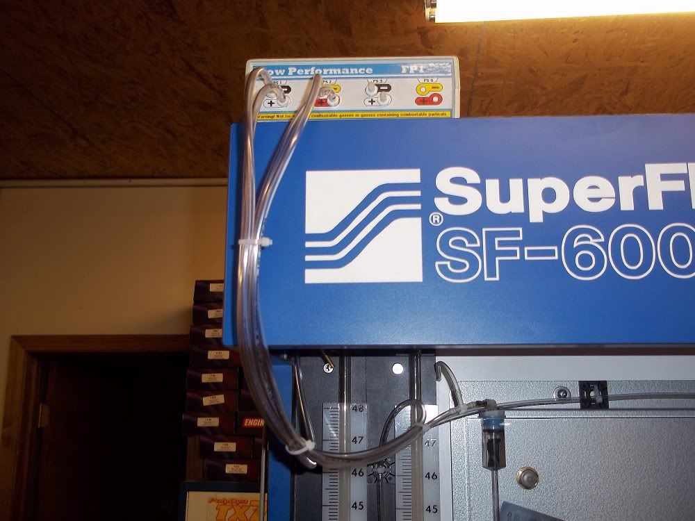
I do know that these two pictures are my best friends in this experiment!

Soon to be replaced with a PTS DM!


Re: SF Sizes
Posted: Sat Nov 26, 2011 6:31 pm
by jfholm
65mustang393 wrote:
Bruce, I measured as gently as I could with vernier calipers. I'm thinking that's not the preferred method... mind telling me how you recommend I measure the diameters?
Thanks,
Gerald
We used to have a device called a shadow graph if I remember correctly. You would place your item on it and it would accurately project a shadow of the image that you could measure on the screen to the .001". Good luck finding one though.
John
Re: SF Sizes
Posted: Sun Nov 27, 2011 2:06 pm
by 65mustang393
blaktopr wrote:Mustang, how is your velocity probe reading. Based at your current setup. Can you probe an easy area like the pinch trying to keep at a steady depression. Does the measured and probed areas match when using the calculated measurement based on your current CFM numbers.
EX. If I probe an area and get 302 FPS based on my bench cfm, I am at 2.700 sq in.
If I were to use CFM from your bench of my port and apply the cfm # to the CSA calc, I may get around say 2.62. When I measure my port without radius removed I get 2.8. Corner radius about .250 is minus .054. Plus I have a little extra radius on the top and bottom. For sake of argument, lets call it minus .075. So 2.8-.075 is 2.725. So then if that the case, I would question the CFM the bench was showing.
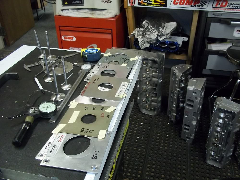
See attached photo. 1.150" wide by 2.010" tall. 1/4" corner radius.
1.150 x 2.010 = 2.3115 sq inches
1/4 square box x 4 = 0.25 sq inches
1/4" radius circle = 0.19635 sq inches.
0.25 - 0.19635 = 0.05365 sq inches taken up by corner radius
2.3115 - 0.05365 = 2.2578 effective square inches of area.
(2.2578 x 309.5 fps) / 2.4 = 291.16 cfm
Read 286.5 so about 1.6% low.

