Page 1 of 1

Posted:
Fri Mar 10, 2006 5:52 pmby SuperRunner
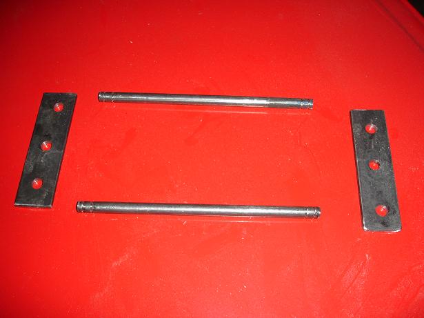
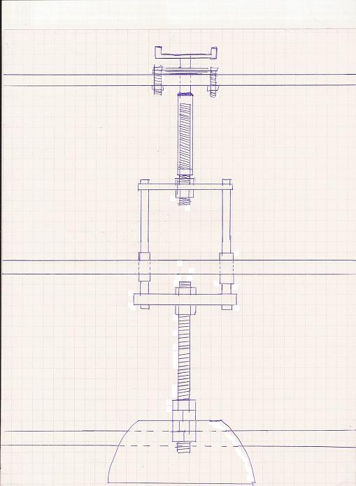
I have been trying to think of a good way toI have been trying to think of a good way to operate the air valves, I just really don't like how the MSD and Mercdog designs are. This this is what I have come up with.
For sealing, at first I thought I had closer tolerances on the slider assembly,
but after duburring the inside, they are a lot further than I had thought, so now I have to derive some sort of seal for it, I am thinking I can probably do a cap with an o-ring in side, and silicon that to the outer slide tube.
Posted:
Fri Mar 10, 2006 11:23 pmby Thomas Vaught
That is actually a pretty good way to transfer motion to the actual valve and at the same time
tighten up the tolerance on the shaft to sleeve
(guide) in the bench.
Tom V.
Posted:
Sat Mar 11, 2006 2:20 amby SuperRunner
Oh, I also wonder...how far do you guys move your valves to be fully open? I am going to have about 4-5 inches of movement.
Posted:
Sat Mar 11, 2006 10:45 amby 86rocco
This is just a guess based on some very crude math but I'd say flow through a valve of that type would probably max out when the travel reaches about 1/2 the seat diameter so unless you're using emormous bowls, 4" should be lots
Posted:
Sat Mar 11, 2006 1:22 pmby Thomas Vaught
Another design with a similar strategy is to use a pair of the sliding "waste" valves, connected with a bar like you have shown. The actual plenum box is made shorter width wise and the air comes in the sides of the lower plenum. This eliminates any leakage between the upper and lower plenums that is there with the MSD design.
Tom V.
Posted:
Sun Mar 12, 2006 2:01 amby SuperRunner
Posted:
Sun Mar 12, 2006 2:35 pmby Thomas Vaught
Nice.
Tom V.
Posted:
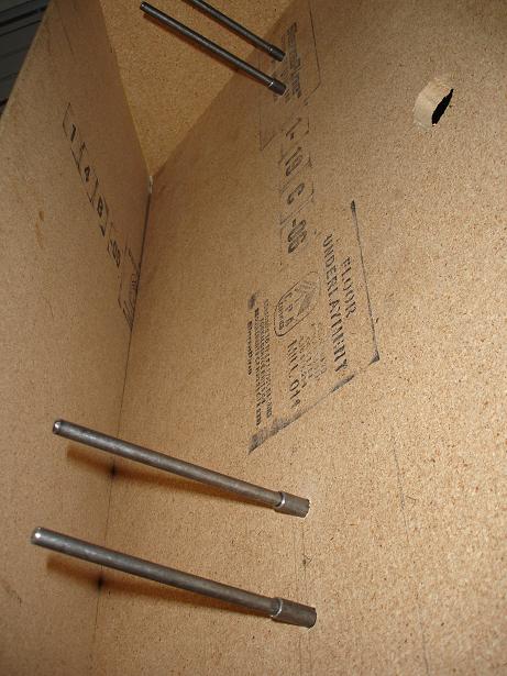
Sun Mar 12, 2006 7:36 pmby SuperRunner
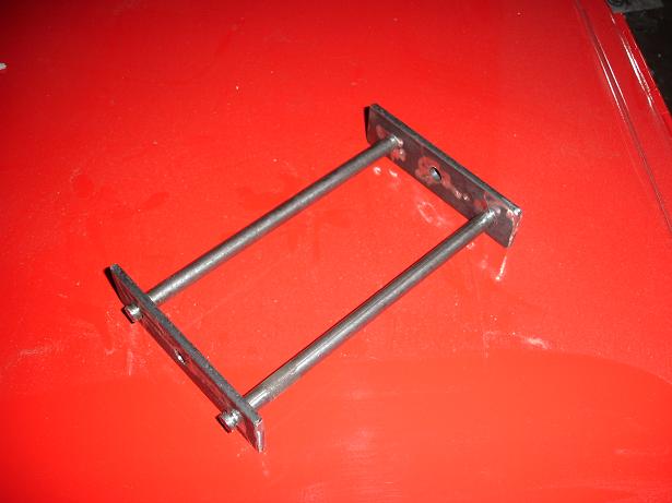
Took me forever to put this together. I am using E-clips to hold it together, and I had to cut out all the groves with a dremel. One day I will get a lathe
Posted:
Sun Mar 12, 2006 8:38 pmby larrycavan
You put a good effort into the valve setup and it looks great.
In all honesty, it didn't have to be that complex though. It looks as if you didnt like the fact that the valves spin in and out of their seats. If I were doing mine over [there's really no need because they work fine] I would only make one simple mod to them.
They would still spin and the rod would go through the center but I would add a simple cross plate with two long thin 6mm bolts. The bolts would support the outer portion of the bowl bottom.
Posted:
Sun Mar 12, 2006 10:02 pmby Thomas Vaught
The Super Flow Valves are made from Aluminum. I would think you could make the same thing from some sort of plastic on a lathe. The metal bowls are inexpensive but may need "extra" stuff like Larry mentions.
When I made a valve from a rubber toilet plunger, I stuffed a circular piece of wood in the end flush with the plunger. This allowed me to have a threaded piece of wood (where the handle screwed in normally) and a second piece of wood that would support the plunger better. I had lock nuts on both sides of both pieces of wood. I think the wood cleaned up the air flow around the plunger too.
Tom V.
Posted:
Mon Mar 13, 2006 1:14 amby SuperRunner
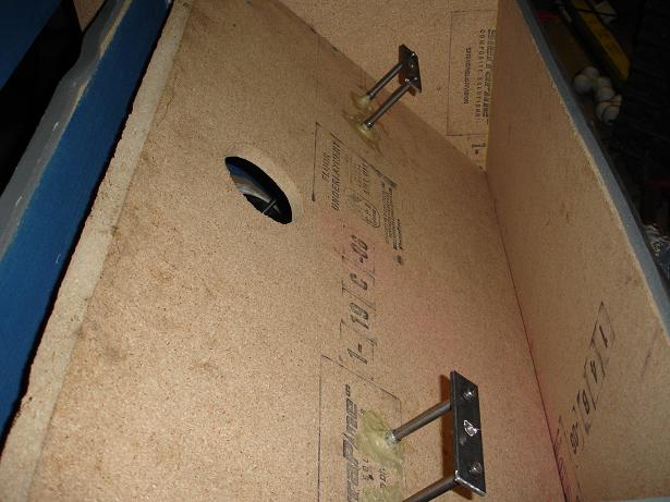
Actually I didn't even think of the bowl spinning into the seal, it was more that I wanted the handle to stay stationary, not move in and out with the valves. So I had to have a threaded coupler inside somewhere, but in order for that to work, the bowl couldn't spin or it wouldn't move up and down the threaded coupler. But now that you mention the whole spinning into the seal thing, that is just an added bonus. These things seal in sooo tight. I also reversed the bolws to each other so the air pressure will actually cause the bowl to sit firmer in place. The positive pressure bowl is in the lowest chamber with the motors, and the negative pressure bowl sits in the lower plenum chamber. The more pressure, the better it seals.
Posted:
Sun Mar 19, 2006 12:37 pmby Kyrasis6
If you took the rubber plunger, made a wood cap to go on the end like mentioned before then filled it with some of that great stuff foam it would be very solid and still seal good since its rubber.