Could someone please draw me a diagram for a vertical manometer with a resevoir also showing the connections for inlet and exhaust testing.
Sounds daft but i need to clarify something.
Thanks,
Doug.
Vertical manometer help??
7 posts
• Page 1 of 1
The simplest way to do it is to use a simple U-tube manometer with two legs made of equal size tubing with a scale in between the legs. One side connects to the plenum of the bench and the other is open to the atmosphere. When you're operating the flowbench, the fluid goes up on one leg down on the other and you measure from the zero point in the middle to the fluid level. The disadvantage of doing it this way is that your scale is contracted by 50% i.e. a 1/2" along the scale corresponds to 1" of pressure making it a little more difficult to read, the advantage is simplicity, no need to swap tubes or change direction with valves.
If you choose to use a reservoir type manometer, the reservoir is connected to the high pressure side and the long leg of the manometer is connected to the low pressure side. IOW, when intake testing, the long leg is connected to the flowbench's plenum and the reservoir is open to the atmosphere and when exhaust testing, the connections are reversed. With a reservoir type manometer, the scale is expanded compared to the simple U-tube but it's still not 100%, you need to take the size of the tube relative to the size of the reservoir into consideration. My inclined manometer spreadsheet posted can do the calculations for you, just set the "scale length" and "vertical scale height" to the same number. However if you make the surface area of the reservoir VERY large compared to the cross sectional area of the tube, the scale gets very close to 100% and the difference is small enough that you can ignore it then can just use a normal yardstick or something similar as your scale, the way Tony has done in his pictures below.
If you choose to use a reservoir type manometer, the reservoir is connected to the high pressure side and the long leg of the manometer is connected to the low pressure side. IOW, when intake testing, the long leg is connected to the flowbench's plenum and the reservoir is open to the atmosphere and when exhaust testing, the connections are reversed. With a reservoir type manometer, the scale is expanded compared to the simple U-tube but it's still not 100%, you need to take the size of the tube relative to the size of the reservoir into consideration. My inclined manometer spreadsheet posted can do the calculations for you, just set the "scale length" and "vertical scale height" to the same number. However if you make the surface area of the reservoir VERY large compared to the cross sectional area of the tube, the scale gets very close to 100% and the difference is small enough that you can ignore it then can just use a normal yardstick or something similar as your scale, the way Tony has done in his pictures below.
- 86rocco1
- Posts: 292
- Joined: Sun Nov 18, 2007 5:46 pm
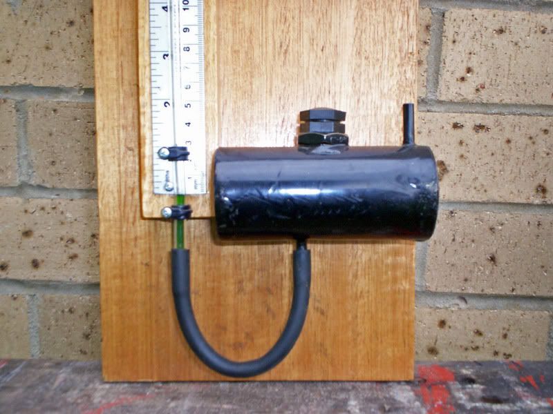
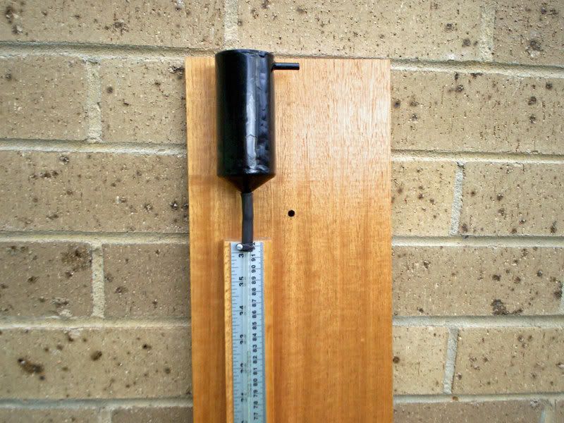
Positive pressure for exhaust testing, goes into the top of the reservoir to force water up the manometer. The top of the manometer is opened to atmosphere.

Negative pressure for induction testing connects to the top of the manometer tube. The top of the reservoir is left open to atmosphere.


Negative pressure for induction testing connects to the top of the manometer tube. The top of the reservoir is left open to atmosphere.

Also known as the infamous "Warpspeed" on some other Forums.
- Tony
- Posts: 824
- Joined: Sat Dec 03, 2005 12:34 pm
- Location: Melbourne, Australia
Thanks guys.
That is just what i was after. Much appreciated.
Just trying to plan out my bench as much as possible before i start construction.
Think i'm going to go for the increased resolution of the resevoir with some nice stainless or ally tanks.
I've ordered a DM but think the water manometers will be a good back up.
- UKDoug
- Posts: 54
- Joined: Sun Jul 27, 2008 4:00 pm
A digital manometer is an excellent idea Doug, but it will still need to be initially calibrated and checked against something.
The thing to remember when building a reservoir is that it is the exposed fluid surface area that really matters, not the fluid volume.
So try to fill the fluid up to the widest, broadest part of a cylindrical tank if it is mounted horizontally. That one in the picture is two inches diameter four and a half inches long, giving a massive nine square inches of fluid surface area.
The fluid can rise 1,000 mm up the tube, but falls less than 0.5 mm in the reservoir when it does.
Also known as the infamous "Warpspeed" on some other Forums.
- Tony
- Posts: 824
- Joined: Sat Dec 03, 2005 12:34 pm
- Location: Melbourne, Australia
7 posts
• Page 1 of 1
Who is online
Users browsing this forum: No registered users and 2 guests
