Page 10 of 23

Posted:
Tue Oct 07, 2008 1:03 pmby Otto
remember under boost the intake will tolerate a later closing intake than a n/a befor it can no longer stuff it in and get reversion expecially at rpm but what do i know i'm a bike guy
Posted:
Tue Oct 07, 2008 3:30 pmby 106-1194218389
Posted:
Wed Oct 08, 2008 1:15 amby Otto
Posted:
Fri Oct 10, 2008 11:15 pmby 200cfm
Did some flow work on the heads for the 330 motor and made some gains. Bruce, I wear you PTS hat when flowing and it may be influencing the values 
While flowing and studying my work and later working in the garden thinking about air and port shape how things work in nature and why, etc. I had a thought about the throat area and size. My mind started thinking of the throat as an "orfice plate" and wondered if that is a correct view. I have read of it as a nossle or ventri area lilke in a carb but never any talk of it serving and perhaps behaving like a orifice. It is difficult to measure my throat because it is not a perfect circle but I came across a washer that indicates I am around 84-85 % valve diameter. If one calcualtes the cfm flow for that opening using the orifice flow calculator is that data useful for understanding port flow? Or in comparing that data with the bench cfm data say at max lift? Is there any correlation possible here?
Posted:
Fri Oct 10, 2008 11:58 pmby 106-1194218389
Posted:
Sat Oct 18, 2008 10:30 amby 200cfm
My cut up red head test port is still at the machinist so no data to gather on that yet. Patiently waiting for service. Finished up one head. Flow peaking around 178 to 180 at .525" lift. Measuring the speeds at .450 lift shows.
PRT
350 350 331
350 331 324
344 331 300
SSR
362 356 362
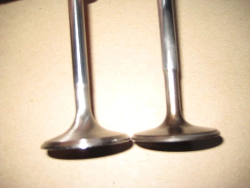
Down the middle it averages 310 to 325 depending on the depth area. Made a comparison of a new stude tulip valve to the current sbc valve and the tulip valve flowed better. Does that mean my throat is to big?
1.85 vs. R-3 valve
Lift CFM CFM Gain
0.100 60.1 58.9 -0.3
0.200 102.3 104 1.7
0.300 138.8 141 2.2
0.350 153.5 157.5 4
0.400 165.6 167.8 2.2
0.450 173.6 175.1 1.5
0.500 180.8 179 -1.8
0.550 181.8 181.9 0.1
0.600 182.6 183 0.4
Seems to favor the tulip shape over the reduce stem and flat back valve.
Posted:
Sat Oct 18, 2008 1:47 pmby 106-1194218389
[color=#000000]Have you tried a 35
Posted:
Thu Oct 30, 2008 11:43 pmby blaktopr
The one thing I would like to know and find out is ,
Does the port like the tulip because it lets the air transition through the seat better into the chamber
Does it like it because of the wider seat cut on the tulip valve
Does it like it because of the larger stem before the tulip and not the tulip.
Does the larger stem and tulip take up some area in the bowl/ seat area like 200 questioned, changing the speed through the seat.
I'll be thinking of these things even when testing my heads.
Posted:
Sun Nov 02, 2008 12:54 amby Otto
Posted:
Mon Nov 03, 2008 7:09 amby blaktopr
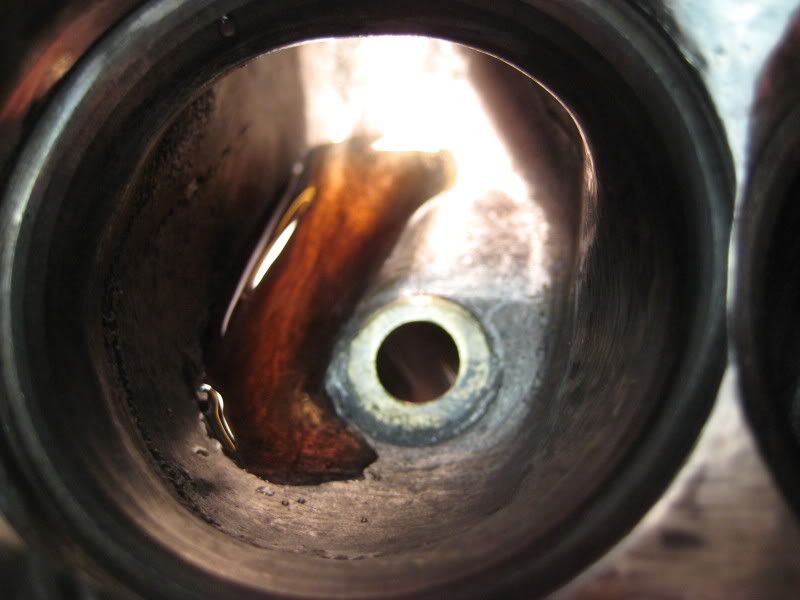
Quick before work. I would look at the velocities over the ssr before filling back up. Many others have mentioned the importance of that over airflow gains. Looking down the port, I see what you mean about the vortex "wing". In my testing, as speeds go up, the straighter the airpath. With that port, it looks like that air would aim right at that spot at the guide. Gets really tight there. I would be interested to hear if anyone may have some other dyno test info that may show that what you done may be a positive, even though you are down on flow. Time for work.
Chris
Posted:
Mon Nov 03, 2008 7:41 amby bruce
Curious why you don't use some modeling clay to fill in those areas for testing?
Posted:
Mon Nov 03, 2008 3:11 pmby 106-1194218389
Tom,
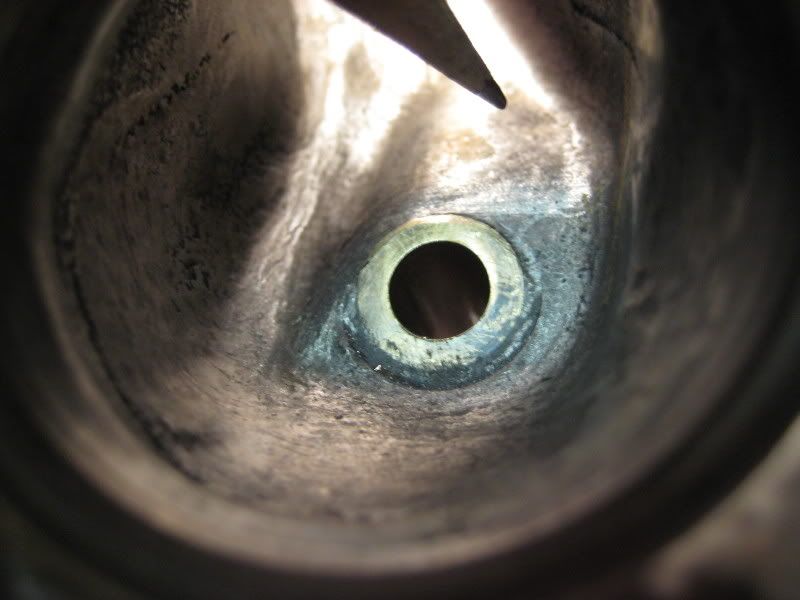
Bruce is correct, just use modeling clay for preliminary testing - also you port reminds me of the standard Chevy Vortech heads which we tried on the dyno and they died at 4500 RPM - Too much swirl. Your port looks like it has a real dog-leg in it. It the bowl itself there seems to be quite a protrusion on the side of the wall above that ramp. On your cut head have you tried making that part of the bowl bigger. I would think the bowl itself needs to be bigger and try to make the port more like a conventional port. Take a look at those port molds I did. I know you cannot make that port like those but you will get the idea.
John
Posted:
Mon Nov 03, 2008 8:46 pmby blaktopr
My take on it is the wall oposite the "vane" has a sharp bend. At higher speeds, Air won't navigate that well like on a ssr. I look at that wall sideways and feel if you did fill in the roof like you show in the pic that the air would speed up even more really helping the air choose that vane, and producing a higher rate of swirl and turbulence. What is behind that turn? Can the radius be increased. If you can increase or layback that turn then to fill the bowl to match the vane may work well. That amount of dogleg looks to make a dead area maybe trapping fuel in there never letting it escape at high airspeeds. At the instant the valve opens may draw some in but then it may not be as mixed well compared to the rest of the charge, leading to more problems in the chamber.
Chris.
Posted:
Mon Nov 03, 2008 10:16 pmby 200cfm
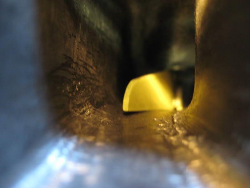
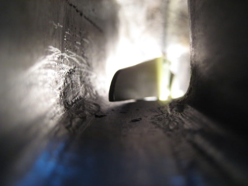
The turn on the left side of the photo with dye water in the channel is the head bolt turn. Don't know how thick that area is but yes, I see your point in laying it back some and making it straighter. The protrusion buldge on the wall on the right side of the photo where the guide ramp exists is part of the water pocket that also goes under the center divider section for the intake/exhaust. I expect that area is getting thin already. I could lay it back but very hesitant too until I know how much meat left there.
Wonder if that $200 sonic tester import from WVA ebayer would give valid reasons for these water cavity areas?
Would be nice to see the port on a sbc vortex head.
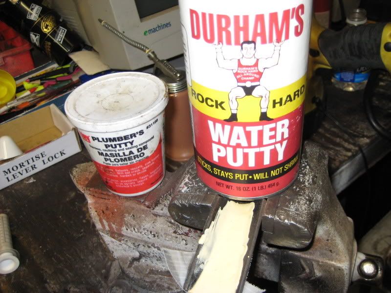
I am going to have to find some better clay. Current clay is rather dry. Must have dried out on the boat getting here. It doesn't stick well or mold easily. On the above water putty container. That stuff dried ok. Not rock hard. You can finger nail scratch it by tapping it. Sands poorly and gums up on filing with a file. Soaked it in gas though and it stayed firm and resistant. Adheres well to iron. Filled two drilled holes in the iron nicely too. That's all I learned about the stuff.
My beloved "red head" was still pending at the machine shop after six weeks. So I went and picked her up today. Felt that 6 weeks was to long to wait for a one chamber valve job. Will do it myself now with the new tooling and pay myself.
tom