Page 11 of 23

Posted:
Mon Nov 03, 2008 11:26 pmby 106-1194218389
Tom,
Another thing you could do on the head you cut up is just drill a 1/4" hole in the bulge in a couple of places to see how thick it is and then port the test head that is cut up and just put clay in the holes when you flow test.
John
Posted:
Tue Nov 04, 2008 1:37 amby Otto
i agree that right side bulge is not helping drill and clay like john say's we are talking sand casting's they could just as easily be solid there and looks to be creating a secondary pinch with the the dogleg and reducing bowl volume i looks lke it needs to darn near straight from the casting seam at about 1:30 to about 3:00 or just past inthe bottom photo but I'm a bike guy
Posted:
Tue Nov 04, 2008 7:11 amby larrycavan
I just cruised the last couple pages real quick so I'm not fully up to speed at the moment....
The turbulence IMO is being caused to a large degree by the too rapid expansion of the port. I see this all the time in certain heads I do because they are both bent and shaped for swirl.
Get some clay, go in there and fill in that section prior to where your pencil is pointing and things should calm down. Clay will show you a great deal about what works and what doesn't for picking up CFM. Curved ports are a mother when you start giving them bowl volume on the fast [curved] side. Things get off balance real quick....
Posted:
Tue Nov 04, 2008 1:39 pmby 106-1194218389
I tried to find photos that would show what the early Vortec heads were like as they had a ramp in them. All the Vortec head pictures I find now are the new style which is similar to a regular SBC head - Sorry I tried. AMC had a similiar head on the intake if I remember correctly.
John
Posted:
Tue Nov 04, 2008 3:51 pmby 49-1183904562
Tom,
Go to the Depot and in the electrical section they sell a clay that is for sealing arond open wires, Made by GB products and comes in a 8 X 2 X 1 bar. It is oil based sticks well and will stay soft for years. I also use the same clay for checking Valve to piston clearance.
Rick
Posted:
Tue Nov 04, 2008 8:53 pmby larrycavan
If this is a test head, here's what I'd try.
Between the yellow arrows, loose all that casting slag. Get a better radius shape to the bowl. Get back under the seat as much as you can. Radius right on around so the front of the bowl has a radius under the seat as well. I've picked up a bunch of flow using that method before.
On the right, fill with clay, the section in grey. Also, there's a bunch of low spots and waves in that beveled portion of the bowl. Clean that up and radius over that straight up wall better. Loose as much of that wall as you can.
Blitz that ramp on the right side of the guide and get some more area there in the roof.....
Anyway...those are the things I'd do if that was a test head.
Edited By larrycavan on 1225846733
Posted:
Wed Nov 05, 2008 12:17 amby blaktopr
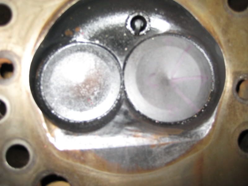
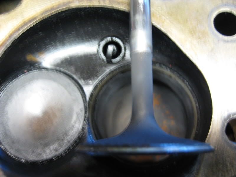
Here is my take from testing and my mouse is crap! As you read this, look at the black areas as fuel puddleing and not being burned thoroughly leaving the sooty black residue. The cleaner spots, had higher speeds keeping some fuel more suspended, until a radical speed increase, dropping the fuel out. I tried to illustrate the pic. Blue lines airflow. Red lines, faster airflow. Magenta, even faster around plug. Yellow is fuel. The three yellow lines on lower right hand corner leading to the quench pad would be under turbulent conditions with larger droplet size congregateing on the wall below it. I am only speculating this without testing your head, but referencing to mine, so don't kill me. The black spot between the two valves and below the plug is where the fuel vortex is and is loose fuel. Burned slower with less O2, so black. Clean ring across plug where speed of air and fuel matched out of seat area, more burned uniformly. Dark area over that clean ring, speeds fast out of seat driving some fuel to ram in and pile up a little then being pushed around toward the exhaust but unable to be drawn back into the fast airstream so just stays there as a thinish layer. Same goes for under the intake toward the exhaust. ( I am referencing top/bottom to the pic only.) The two paths meet on the cylinder wall. Some of the blacking on the exhaust valve, fuel just slowly trapped and moving around in a circular pattern and side to side. Black at the edge of the exhaust valve same side of intake, (no yellow, sorry) fuel separating as speeds increase across the margin. Yellow dots around intake valve, fuel droplets stuck to the edge of the seat cut and margin. Dark area around intake at chamber wall over cylinder wall, same high airspeed, fuel separation as other spots of chamber. Most chambers are smooth, yet to combat some separation problems in the runner, we make it very course. The chamber is treating the fuel as if you polished the intake runner.
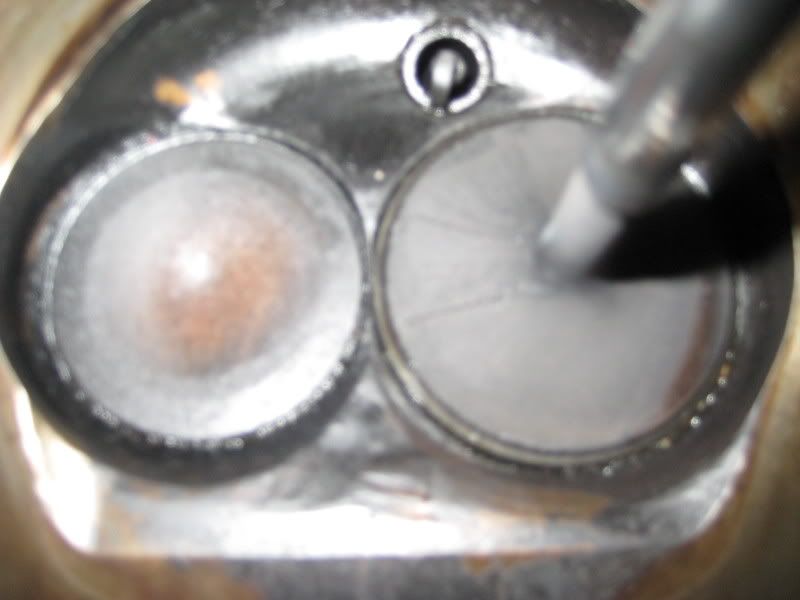
As for the spot on the valve inside the runner, over the severe dogleg, That I think is there because at the higher airspeeds not only does air not want to make that sharp turn, but also the fuel. So both tends to follow the straightest path to the valve and not even touching that section of the valve. If any fuel separates to behind that buldge and forms on the walls, the airspeed is too slow back there and the high pressure area pushes it down along the wall utilizing only the seat and not the face of the valve, therefore not touching that part to leave any fuel and depositing it in that area in the chamber on the wall side.(I think I have the port bias right) Leaving the black deposit. Just trying to contribute.
Chris
Posted:
Wed Nov 05, 2008 12:32 amby blaktopr
Just want to add now myself looking and reading. Concave bowl on exhaust with angles leading to margin I see. Not only does the dark ring closest to intake valve have fuel separating there, as air/fuel crosses over margin and the angles leading to the "bowl" of the valve, the same conditions happen as does over the plug. After the fuel drops out it stays in that void. I guess that it takes less work to reside on the surface of the valve than to re-enter into a fast moving airstream running across the face of it. I know that should be an area of higher pressure, but it must be the same as throwing a plastic bag into the spray of a garden sprayer or why when you try to flick a cigarette butt out an open window, but just ends up coming back and landing in the back seat. 
Posted:
Wed Nov 05, 2008 3:12 pmby blaktopr
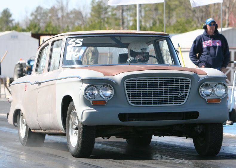
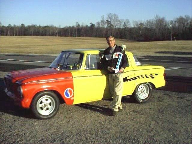
Wow Tom, you don't see that everyday! Glad to see you are able to make the out of the ordinary work well. Man, that car can make some guys cry on the street. I wonder if anyone can chime in on my readings letting me know what I may be missing to continue learning. Plus I don't want to steer anyone in the wrong direction.
Chris.
Posted:
Wed Nov 05, 2008 3:21 pmby 106-1194218389
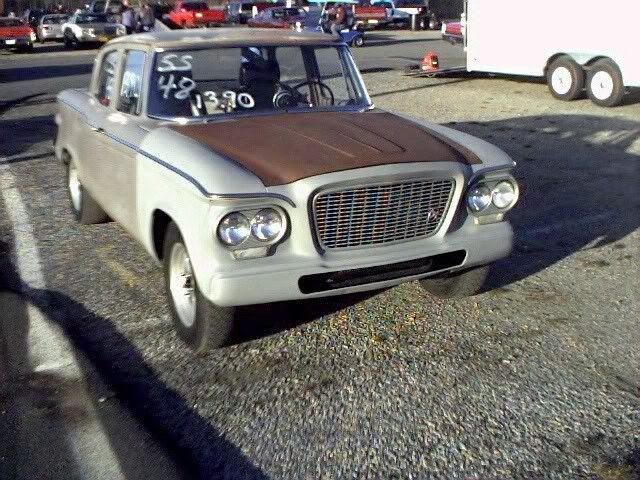
Tom,
do you still have that Lark? That is a cool car. I always loved those - I had a friend that had a supercharged version that was a black 2dr hardtop with a 4 speed.
John
Posted:
Wed Nov 05, 2008 6:41 pmby larrycavan
Which Ve calc method did you use in PipeMax?
Posted:
Fri Nov 07, 2008 11:28 pmby 200cfm
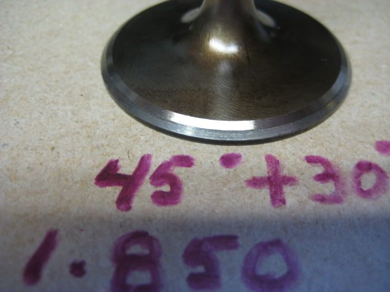
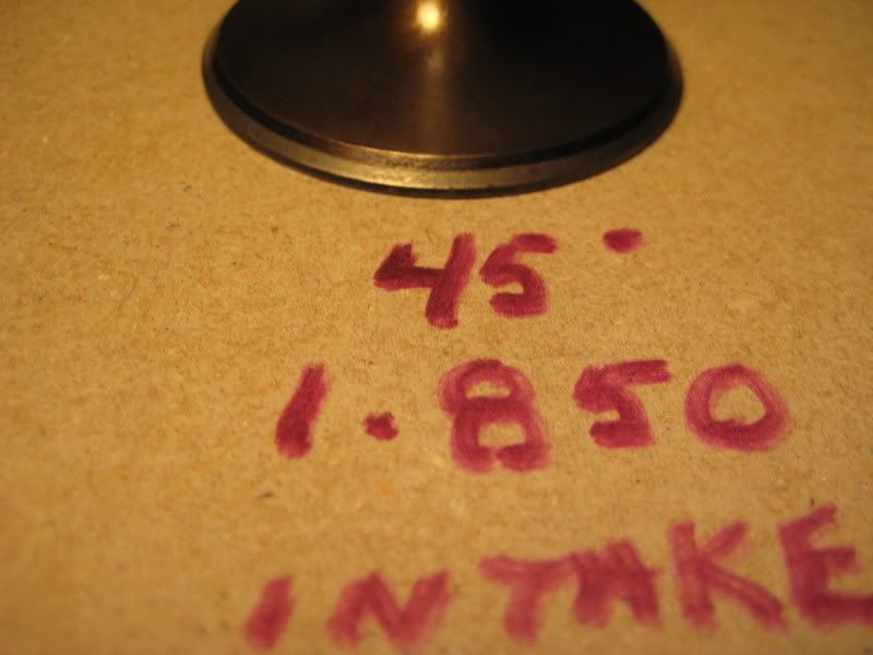
Finished up the heads for now and they are ready for install on the short block. Very pleased with the gains. Took much longer than I anticipated (over 4 weeks) but if I don't stop now I want have time to track test before the season shuts down. I applied a 30 degree backcut to all the intakes and the exhaust with the B & D valve refacer. Used the old stone pending the arrival of the Goodson stones. Didn't touch up the 45 part in the head or the valve. Just lapped those parts together. On speed tallk the don't like lapping but that's all I have used in the past.
Now on this 30 cut, I was surprised and pleased at how so little a cut or angle could have such an influence on the flow numbers. I flowed several ports with the 30 cut and they all posted gains. Very evident from the incline rise values on each lift. Only the .100 lift offered no significant change, but the others took off nicely. This will be my first set of heads with a backcut. The backcut also helped the exhaust numbers. So both were a win/win. Here is data on one of the best ports.
Port 4 (45) Port 4 (45 + 30 backcut)
LIFT CFM CFM gain
0.100 60.3 60.5 0.2
0.200 101.5 109.8 8.3
0.300 138.7 149.8 11.1
0.350 155.5 163 7.5
0.400 165.9 171.5 5.6
0.450 174.8 178 3.2
0.500 178.6 181.2 2.6
0.525 178.8 181.6 2.8
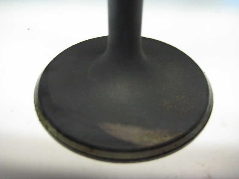
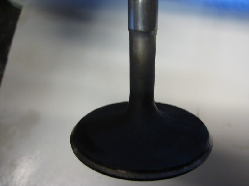
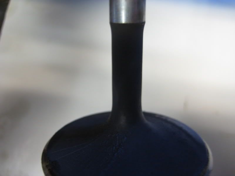
Here is a before and after of the above valve after cleanup.