Is there any advantage of wiring a 240v 2-stage motor in series? If it's rated at 6 amps, would it be necessary? Use the relays like SF, but have 240 motors instead of the 110v, 923's? Just curious..
Chad
240 volt vacuum motors - fan search.
Just some further comment on the construction of these two commercial blower rotors.
Blower number #1 was originally rated at 300 CFM and 17 inches flow standard. It had a direct coupled 1Hp motor, which turned the rotor at 2850 Rpm (50Hz power here).
Inlet eye size 3.5 inches, discharge from the snail volute 2.75 inches. Rotor diameter 18 inches, consisting of two flat steel sheets spaced half an inch apart at the outer periphery, and slightly more widely spaced near the centre. Short straight blades only three inches long hold the two flat drive discs apart.
The way the rotor is constructed, the flat disks have short narrow radial slots punched in them, and the punched vanes have tabs which project through these narrow slots. The tabs are bent flat and either welded (or brazed ?) to the two flat steel discs.
I modified this blower by replacing the direct drive motor with pulley drive which had a speed step up ratio of 2:1. I then used a 10 Hp 2850 Rpm three phase motor and a variable speed drive to run the rotor up to 5,700 Rpm.
Flow almost doubled to around 550 CFM. Pressure went up four times to 65 inches, and drive horsepower increased eight times to approximately 8 Hp. This blower is currently what I am running in my bench.
I have recently purchased blower number #2. This one already has pulley drive, and the original standard ratings are 450 CFM at 19 inches pressure. The pulley ratio is (4.25/3.75) 1.13 speed step up. The 3Hp (oversized) motor runs at 2850 Rpm, and the blower rotor at around 3230 Rpm.
The rotor is very similar to the first one in all respects, but the construction is different. The vanes again are straight radial, but are simple flat metal strips folded into a Z shape. These are spot welded to the inside of the rear disk. The front disk is then just placed on top, and pop riveted in position.
Higher rated airflow seems to come more from the generous internal flow paths than the actual rotor dimensions. The inlet eye is four inches, and the discharge is three and a half inches.
I plan to not use pulley drive on this second effort, but directly couple a 15 Hp motor rated at 2850 Rpm. I then plan to run this motor up to double it's rated speed by running my variable frequency drive up to 100 Hz. That will get rid of the pulleys and make it a far more compact assembly. I have not purchased the 15 Hp flange mount motor yet, but have sourced one for $200 from a machinery yard and will, probably Monday.
With a bit of luck this second blower should give me perhaps 800 CFM at 60 inches, with some very nice pressure/flow characteristics. If the rotor does explode, I can make a stronger one fairly easily using thicker gauge metal and better construction.
The outer volute on the first blower is two cast iron halves. The volute on the second blower is pressed mild steel sheet, again, two halves bolted together.
Also known as the infamous "Warpspeed" on some other Forums.
- Tony
- Posts: 824
- Joined: Sat Dec 03, 2005 12:34 pm
- Location: Melbourne, Australia
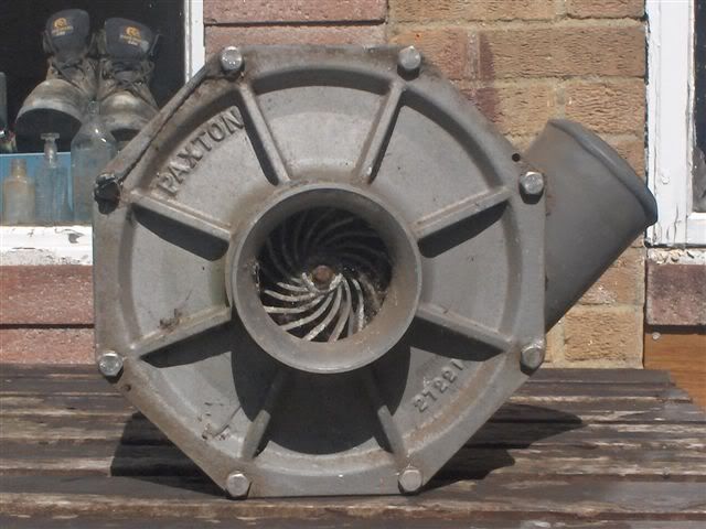
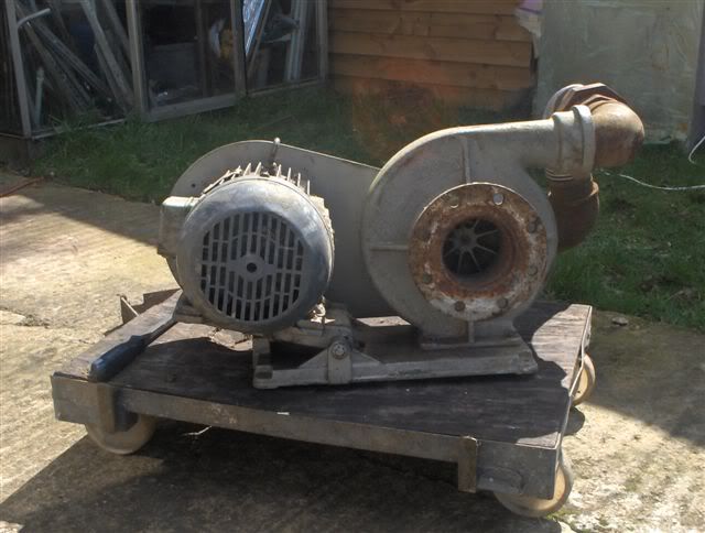
oh and of course the big question ..which is the better one to use ?? .the paxton had a rating of 800cfm at 2 psi 15 bhp motor running at 3500rpm. so what would i need for 400 cfm at 1 psi / oh decisions decisions!
well!! i'll be blowed!!
- ivanhoew
- Posts: 32
- Joined: Wed Feb 08, 2006 3:05 pm
- Location: oxford england
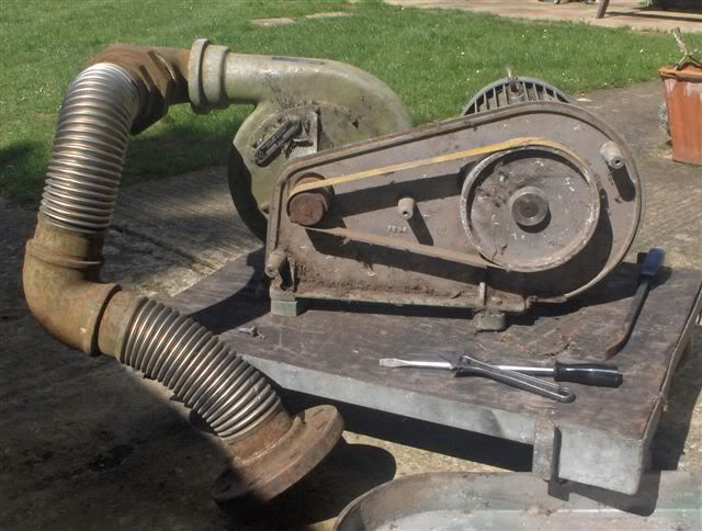
As you can see by the different sizes of the pulleys (blower pulley vs the motor pulley), the step up ratio is pretty high.
10,000 rpm for the paxton blower is not a high rpm when typical automotive superchargers (which are even larger) routinely run 65,000 rpm when driven by the crankshaft.
The Paxton supercharger was used for years on diesel powered submarines to ventilate the different compartments once the sub came to the surface.
C.J. Batten (a famous head porter) at one time had three similar Paxton type superchargers for three flow benches in the Detroit area. A have posted about them in the past. The were used with different sized sharp edged orifice plates for flow ranges. The flow came from the flow bench to the inlet of the supercharger and then was controlled by a throttle on the discharge side.
Tom V.
- Thomas Vaught
- Posts: 465
- Joined: Fri Feb 18, 2005 5:36 pm
- Location: Michigan
Ivanhoew, your scrap yard sure beats my scrap yard !
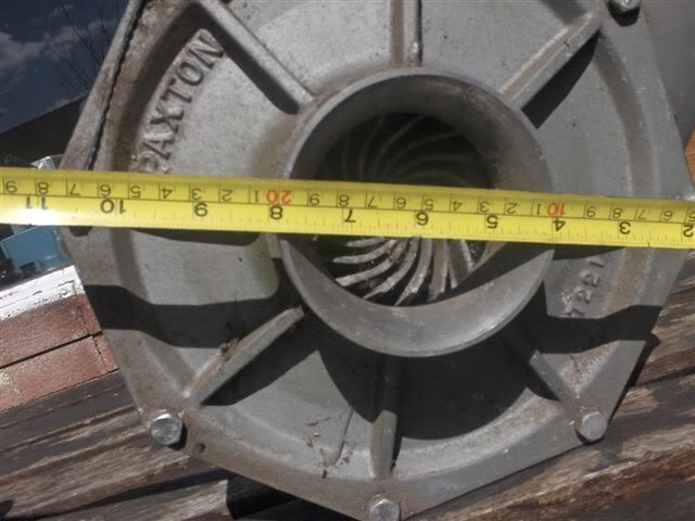
The Paxton looks like the one to try first. Paxtons have an internal step up gear ratio of 4.4:1 and that is well worth having. The required external pulley ratio will be far more sane.
That 5Hp motor really requires proper three phase power, and the easiest way to get that is from a variable frequency drive. I believe 5Hp VSDs can be found that will run from single phase power, but the current draw is going to be fairly heavy doing it that way. Your best bet might be to try and get three phase power connected to your home. Ask a local electrician how that may be done. If your friendly electrician spins some story about installing a monster heat pump or airconditioning system, or a huge electrically heated spa, it may be possible to get three phases connected to a home residence. I did exactly that myself, many years ago. The supply authority usually will be fairly enthusiastic, because they think you are going to be buying a LOT more power.
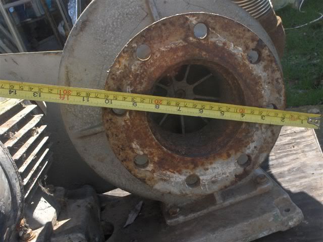
The second blower looks pretty good too, it has obviously been used for something fairly similar in the past. From the pulley ratio, the Rpm must be astronomical, but it seems to have survived o/k.
I have had a lot of grief from high speed belts, my 10Hp 2:1 step up used a dual 8 inch "A" pulley driving a dual 4 inch pulley. The belt speed is very high and it still slips badly. Three or four row pulleys would be better. That is why I have decided to go back to direct drive and run the motor faster.
Picked up my 15 Hp motor Friday, it is quite a monster it says 75 Kg on the rating plate, and I can believe that. 2930 Rpm at 21 amps/phase. The bearings fitted to it are rated to 5,300 continuous Rpm which is ideal. It looks like the easiest way to fit my blower casing to the motor is going to be to turn up a whole new motor end plate out of a big chunk of aluminium. I may build a new rotor for it completely from scratch, but haven't decided yet.
Also known as the infamous "Warpspeed" on some other Forums.
- Tony
- Posts: 824
- Joined: Sat Dec 03, 2005 12:34 pm
- Location: Melbourne, Australia
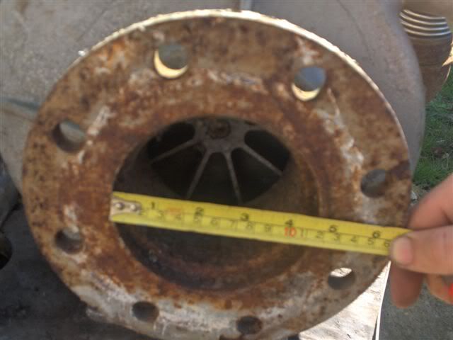
Anatoli, not sure what I am actually looking at from that photograph, and I cannot read the steel ruler.
But you are right about the belt drive. Toothed belts can be fairly noisy at high speeds and loads. But a pair of gears and a belt salvaged from an old OHC engine would be a very cheap way to get a slip free 2:1 ratio drive. But 2:1 is all you are going to get, and buying different sized toothed pulleys new is going to be horribly expensive.
The multirib flat automotive belts would be much more silent, and various alternative ratios would be a lot easier to achieve at reasonable cost.
Ordinary V belts are ugly and inefficient, but they are the cheapest and simplest of all to get working quickly. They are good for a quick try on something experimental, but are not a good long term solution.
Also known as the infamous "Warpspeed" on some other Forums.
- Tony
- Posts: 824
- Joined: Sat Dec 03, 2005 12:34 pm
- Location: Melbourne, Australia
Owing to a forum I have gone deep to studying of streams and vacuum. Now ideas in hearing: two following one after another chambers of vacuum: why do not use? So I see strengthening depression on the weak motor. We shall consider......?
P/S.. TONY! Morning I put place new blower foto ... Anatolij
P/S.. TONY! Morning I put place new blower foto ... Anatolij
- riga team
- Posts: 112
- Joined: Sat Jan 14, 2006 2:05 pm
- Location: latvija
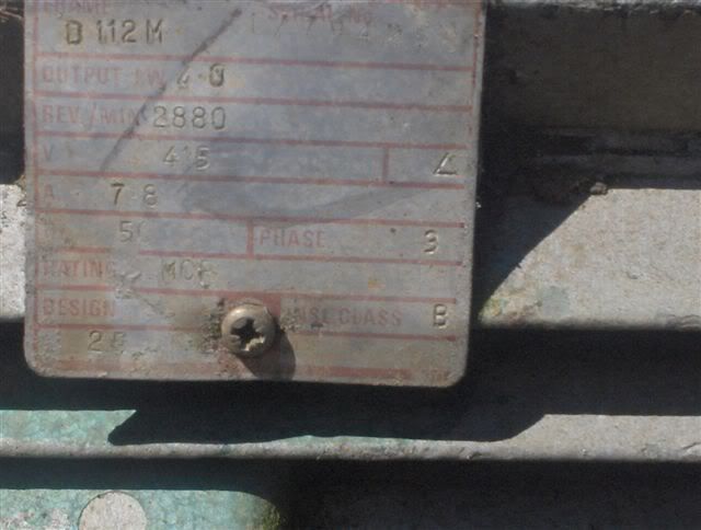
ok , so far im thiking of trying to get the bigger steel cased onew with the motor on it to run ,and see what flies off into the shrubbery .i thuoght i remembered a post on here that dealt with running single phase through a 3 phase motor using a capacitor to throw one winding out of synch to get it to rotate ,i also thuoght someone was talking bout using a piece of rope to start it spinning !! but i cant find any of this now dammit.the pulleys are 2.5 inch on the fan and 8 inch on the motor giving 3.2 :1 ratio ( i think) 11 inch fan and 2880 rpm motor ,gives 2880 *3.2=9216 rpm so 11''*3.14 =34.54'' so 318320.6 inches/min,442 ft/sec.(this may all be total drivel ) so ill have a look to see if anybody has made any posts bout the relation between spped and pressure im sure i saw one somewhere.
regards robert.
regards robert.
well!! i'll be blowed!!
- ivanhoew
- Posts: 32
- Joined: Wed Feb 08, 2006 3:05 pm
- Location: oxford england
oh also tony the paxton has no internal gearbox ,its a direct connection to the fan shaft ,bummer! i appreciate your comments on the scrap yard it cetainly is a goldmine ,one of those rare yards where things go there and dont immediately get crushed.the variable frequency drive unit that may run a single phase supply on a 3 ph motor sounds like a bloody good piece of kit ill try to find one ,but bear in mind i am on a micro budjet!! thanks a lot ,,robert
well!! i'll be blowed!!
- ivanhoew
- Posts: 32
- Joined: Wed Feb 08, 2006 3:05 pm
- Location: oxford england
Who is online
Users browsing this forum: No registered users and 0 guests

