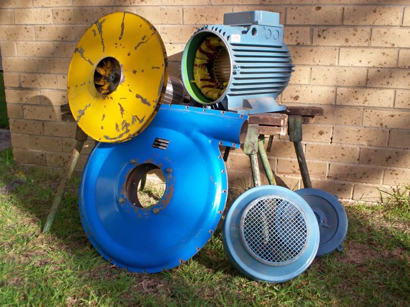
At the moment it is incomplete, being half way thorough yet another upgrade, and being moved to a different location. Although there is enough of it shown here to get a general impression of the design philosophy and construction.
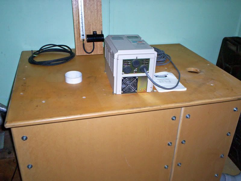
As you can see there are two test holes. The one on the left blows, and the one on the right sucks. Flow direction through the bench is always in the same direction, and that greatly simplifies construction, and avoids a lot of potential problems.
On top of the bench is a 10Hp rated variable frequency drive that can run motors up to 15Hp, provided care is taken to avoid excessive peak loading during acceleration. Also there is the test pressure manometer. The sloping manometer is of similar construction, but is being completely rebuilt at the moment. Later I may go electronic, but not during this upgrade.
The suction test hole leads straight down into a settling chamber, in which is located a two foot diameter orifice turret with eight removable and interchangeable orifice plates.
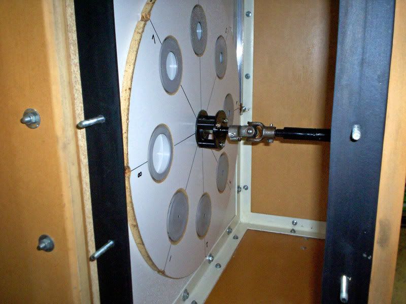
These orifice plates are made from PVC out of standard 90mm storm water pipe, end blanking plugs. These 90mm plugs are a tight press fit into a 3.5 inch hole cut with a holesaw. (3.5" = 88.9mm). The orifice plate holes were bored on a lathe, and there are eight different diameter orifices all with 2:1 flow ranges going from 800 CFM down to 6.25 CFM.
The turret has a self aligning central ball bearing, and rotates on a fixed bolt. There is also a spring to load the turret against the bulkhead, but air pressure also assists in sealing. On the outer circumference of the turret is a spring loaded roller to index the orifice over the hole through into the blower compartment.
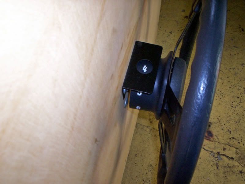
A steering wheel ! on the side of the bench also has a display to show which orifice is in position.
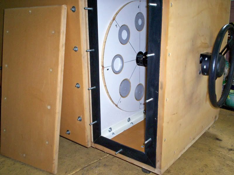
Construction of the bench uses two frames of welded steel angle, with a bulkhead sandwiched in between. The outer panels are all one inch MDF bolted and glued to the steel frame. It has never leaked right from the day it was first assembled.
The front access covers use thick sponge neoprene gaskets, and with a rattle gun, the covers can be be removed in less than a minute, and replaced in less than five minutes. This can be done countless times without any chance of slight leaks developing.
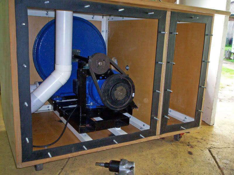
The left hand compartment houses the blower.
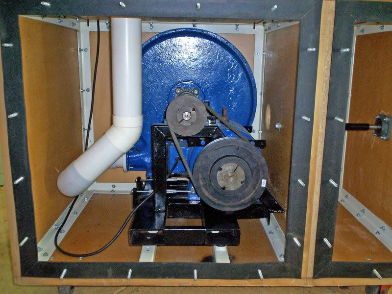
A 10Hp three phase motor drives the blower through a 2:1 speed increase with dual drive belts. It slips rather badly, at least four drive belts should really be used. The problems I have had with this pulley drive system are the main reason for upgrading the blower. My next blower will be the Aerotech, direct driven from a flange mount 15 Hp motor. No pulleys yipeee !!!
The black metal frame of the blower and drive motor, are mounted on very soft springs to reduce noise and vibration transmission through to the outside. Usually the blow test hole is vented outside down a large storm water drain, and the whole bench is as quiet as a small window airconditioner, even when run flat out. That has to be so, because I have some problem neighbors only feet away. That is another fairly powerful reason to relocate the whole flow bench.
